Super TapTo Boy: Difference between revisions
| Line 26: | Line 26: | ||
* A 90 degrees USB-C to USB-A cable | * A 90 degrees USB-C to USB-A cable | ||
* | * A small USB hub for inside the case to hook your devices to. Don't make this too big or it won't fit. Also don't hook up too many (power hungry) devices to it as all of it needs to be powered by the board. | ||
* DuPont cables (female to female) | * DuPont cables (female to female) | ||
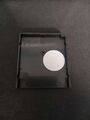
* Round NFC tags (NTAG 215) | * Round NFC tags (NTAG 215) | ||
| Line 36: | Line 36: | ||
'''Optional:''' | '''Optional:''' | ||
* Female USB-A and C ports | * Female USB-A and C ports | ||
* A Bluetooth dongle | * A Bluetooth dongle | ||
* A Wi-Fi dongle | * A Wi-Fi dongle | ||
* | * Some shrink cables | ||
* An Arduino board (Arduino Pro Micro ATMega32U4) for the front controller ports | |||
* Soldering iron and wire | * Soldering iron and wire | ||
| Line 67: | Line 67: | ||
</gallery> | </gallery> | ||
[[File:15.jpg|thumb|254x254px|Super TapTo Boy]] | [[File:15.jpg|thumb|254x254px|Super TapTo Boy]] | ||
[[File:SMB3.png|left|thumb|263x263px|Example custom label]] | |||
At this point you have reached a checkpoint and should you wish, you could continue with the main build or use the Super TapTo Boy like this as a standalone reader via USB. If so, the only thing left to do is to make custom labels for your games and play them. | At this point you have reached a checkpoint and should you wish, you could continue with the main build or use the Super TapTo Boy like this as a standalone reader via USB. If so, the only thing left to do is to make custom labels for your games and play them. | ||
I invite everyone to come up with new and clever ways to display the cases and games. Perhaps designing and 3D-printing a stand that the Super TapTo Boy can be put on or slot into. The sky is the limit! | I invite everyone to come up with new and clever ways to display the cases and games. Perhaps designing and 3D-printing a stand that the Super TapTo Boy can be put on or slot into. The sky is the limit! | ||
| Line 93: | Line 94: | ||
File:Screenshot 2024-09-09 111623.png | File:Screenshot 2024-09-09 111623.png | ||
File:Remix-0bcf1e7b-0318-47a1-8419-039ae7173e7f.png | File:Remix-0bcf1e7b-0318-47a1-8419-039ae7173e7f.png | ||
</gallery> | </gallery> | ||
| Line 127: | Line 126: | ||
--- | |||
''Big thank you to BedroomNinja for making and supplying me with this backplate!'' | ''Big thank you to BedroomNinja for making and supplying me with this backplate!'' | ||
Revision as of 22:43, 9 September 2024
Super TapTo Boy is a custom case project created by Phoenix that utilizes an SNES shell with an SBC inside, designed to work with a Super Game Boy for reading games. The Super Game Boy contains a PN532 NFC reader connected to an SBC (either a DE-10 Nano or a Raspberry Pi), which is housed inside the SNES shell. These components are connected internally via a wired USB connection.
The games' paths are written onto an NFC chip or tag using the TapTo Life app. This chip is then placed inside a Game Boy cartridge, which is read by the NFC reader located within the Super Game Boy. This process initiates the game on the desired hardware. More information on using the TapTo Life app to write games to NFC chips can be found here.
Since the original purpose of the items are being changed in this build (playing GameBoy and SNES games), from here on out I will be referring to the Super Game Boy as the Super TapTo Boy and the SNES (Super Nintendo Entertainment System) as the SMES (Super MiSTer Entertainment System).

Introduction

This project started it's life after contemplating on how best to use physical media together with software or hardware emulation. Since the MiSTer Project and the multitude of Linux-based Emulation operating systems have no physical media for games, a lot of people resort to modding and using their own classic consoles for the most nostalgic looking and feeling experience. Currently software and hardware emulation have come a long way and are in some cases (almost) interchangeable with original hardware accuracy-wise. The absence of physical media keeps people from viewing this route as a 'complete' and authentic experience.
The TapTo project introduces a new way for people to fill this gap with physical NFC cards. Super TapTo Boy tries to improve upon this concept with physical cartridges to replicate the feeling of inserting games and having a classic console to look at while keeping the cost relatively low compared to modding original hardware for the same performance.
The build
In this section, I will discuss the building process of the Super TapTo Boy. As a disclaimer, this process requires some soldering skills and involves cutting or removing parts of your existing hardware. I would rank this process as intermediate. If you enjoy tinkering, read on. Otherwise, consider seeking help from others before attempting any irreversible modifications.
With that out of the way, below is a list of the requirements for this build. Try to acquire as many of these items as possible before you begin.
First, you will need either a European Super Nintendo or a Japanese Super Famicom. The American Super Nintendo might work as well, but due to its different shape and size, and since I do not own one, I cannot guarantee that all steps will work perfectly, so your experience may vary.
Second, you will need a Super Game Boy and some Game Boy cartridges. These can be purchased online or you can use your own cartridges that you want to put an NFC chip into (more on that later).
Preferably, you will also need a 3D printer to print some parts for the build, although these are cosmetic and not mandatory.
Additionally, you will need some cables and other items. Keep in mind that we have limited space in the case, so the smaller or shorter the items are, the better:
Mandatory:
- A 90 degrees USB-C to USB-A cable
- A small USB hub for inside the case to hook your devices to. Don't make this too big or it won't fit. Also don't hook up too many (power hungry) devices to it as all of it needs to be powered by the board.
- DuPont cables (female to female)
- Round NFC tags (NTAG 215)
- A PN532 NFC reader with USB-C (black one)
- General tools like a plier and screwdrivers (including 3.8 mm and 4.5 mm Gamebit screwdrivers for the Super Nintendo, Super Game Boy, and Game Boy cartridges)
- Double sided tape (I used 3M heavy duty tape)
Optional:
- Female USB-A and C ports
- A Bluetooth dongle
- A Wi-Fi dongle
- Some shrink cables
- An Arduino board (Arduino Pro Micro ATMega32U4) for the front controller ports
- Soldering iron and wire
Readying the Super Super TapTo Boy
Steps:
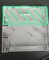
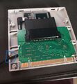
- Open the Super Game Boy: Open up the Super Game Boy and remove everything, including the PCB board. Take the back of the shell and cut some of the support bars to make room for the NFC reader. Cut everything in the green area.
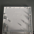
- Prepare the Shell: After you're done, it should look like this. Ensure the cut areas are flat and won't scratch the back of your NFC reader. You can sand these off, but be careful not to overdo it.
- Position the NFC Reader: Position the NFC reader to the back of the Super Game Boy case as shown. Ensure the NFC reader is positioned so that the USB-C cable can still be plugged into it. I made the mistake of placing the NFC reader too flat in the center, which caused my USB-C cable not to fit anymore. Test the position with the cable and the NFC reader to get it just right before applying the double-sided tape.
- Adhere the NFC Reader: After finding a good position where both fit, adhere the reader to the back. Note that having the NFC reader on the shell doesn't guarantee it will read the NFC tags in your cartridges because the cartridge slot remains in a fixed position. You can adjust by applying the tags slightly more to the right in your Game Boy cartridges to compensate for any misalignment.
- Align the NFC Tag: Depending on the position of your NFC reader, you may need to adjust the position of the NFC tag in your Game Boy cartridges to align as much as possible. This will give you the highest chance of a successful scan and game read. It doesn't matter if the NFC reader is off-center, as long as the NFC tag is in a similar position.
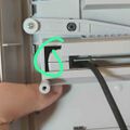
- Cut an Opening for the USB Cable: The final step for the Super Game Boy is to cut a small opening for the USB cable to fit through. I initially tried routing it through the button, but that didn't work well as the cartridge slot of the Super Nintendo didn't accommodate it. If you cut at a low position as shown in the picture on the right, this cut won't be visible once the Super Game Boy is inserted into the case. I deemed this a necessary modification for the project.
- Fit the Super Game Boy into the SMES Case: This is where the USB cable should pass through to get inside the SMES case. It requires some wiggling and fidgeting to get it in, so ensure it fits without forcing it too much.
-
 Step 1
 -
 Step 2
 -
 Step 3
 -
 Step 4
 -
 Step 5
 -
 Step 6
 -
 Step 7


At this point you have reached a checkpoint and should you wish, you could continue with the main build or use the Super TapTo Boy like this as a standalone reader via USB. If so, the only thing left to do is to make custom labels for your games and play them.
I invite everyone to come up with new and clever ways to display the cases and games. Perhaps designing and 3D-printing a stand that the Super TapTo Boy can be put on or slot into. The sky is the limit!
I invite everyone to come up with new and clever ways to display the cases and games. Perhaps designing and 3D-printing a stand that the Super TapTo Boy can be put on or slot into. The sky is the limit!
If you want a beautiful case to go along with your cartridges, you can check out the beautiful work done by Anime0t4ku on his page here.
Readying the Super MiSTer Entertainment System
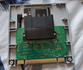
Now we're on to the main dish. If you have stuck around so far, congratulations on making your own TapTo Boy! In this section we are going SUPER and combine it with our Super MiSTer and complete the project. The SMES will house the SBC inside, so a DE-10 Nano or clone board. Keep in mind that as of the moment of writing this tutorial TapTo is not yet officially supported on a Raspberry Pi. This support will come eventually and when it does I will update this section of the tutorial. So if you want a working setup, you will have to use a Terasic DE-10 Nano or one of it's clones (QMTECH, Taki board).
- First thing's first, disassembly! Grab a regular- and gamebit screwdriver and start to unscrew all the screws you see and open up the case and save the screws for later.
- Take out everything on the inside except for the power switch. I personally removed everything except for the power switch and the cartridge slot (I put that back at the end). The reason I kept the cartridge slot was so the Super Gameboy would not jiggle around when inserting and removing the Gameboy cartridges. You can play with this yourself, either remove it, or keep it intact. The eject mechanism was taking up too much space so that will be removed as well. In this build the Super Gameboy will have to stay permanently slotted and as such the eject mechanism will be useless to have. You can remove the cartridge slot for now as it will just get in the way, just put it back in when you're done.
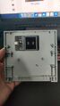
- The next step is trimming! There will be a lot of useless areas in the SMES case that will need some trimming in order to make room for the board and cables etc. So grab a plier and remove as much of the excess plastic as you can (see picture).


Optional: Power Switch
TBD
Optional: Change Shell Logo

Optionally can remove the logo on the top front of the SNES case and paste our custom made logo for this project.
For this you will need to use 100% transparent sticker paper and the Magic Eraser sponge. This will act like sanding paper but will be much more smooth and won't damage the shell like normal sandpaper would. Be patient as this process of 'wet sanding' can take up to 15-20 minutes. If done correctly you will slowly see the original logo disappear.


Optional: Backplate

You can opt to make your own backplate or 3D print one made for this project by BedroomNinja.
Click here to go printables.com to get the 3D printable file.
This backplate is made to be used with very specific parts (as listed above). So keep it mind that if you do not use the exact same parts, I can not guarantee that it will fit perfectly.

---
Big thank you to BedroomNinja for making and supplying me with this backplate!
Optional: Front Controller Ports & LED Light
If you want to use the front controller ports of the SMES you can. It has extremely low latency thanks to it being wired and also supports 1000hz polling rate.
For this you will need an Arduino board, namely the Arduino Pro Micro (ATMega32U4). These can be found on Ali for as cheap as $5. You only need a single one for two controllers, pretty cool huh? This tutorial will assume you want to use both controller ports because, why not? You only use a single board anyway. Remove the front controller ports carefully and take out the attached ribbon cable, we won't be needing it.
Special thanks to MickGyver for making this possible on the Arduino Pro Micro!
Another cool part of this mod is that the power to the front controller ports is the same power that also light the LED of the SMES. So you do two mods for the price of one!

To do this following part you will of course need to solder.
On the right you will see the diagram of the Arduino board. Look at it carefully and solder to the following points.
- LATCH 2 times
- CLOCK 2 times
- GROUND 2 times
- VCC 2 times
- DATA1 1 time (for controller 1)
- DATA2 1 time (for controller 2)
The Arduino board also needs software for it to work with the original SNES controllers. For the software go to https://github.com/MickGyver/DaemonBite-Retro-Controllers-USB/tree/master?tab=readme-ov-file and follow the instructions there.
CAUTION! When soldering on the controller ports, don't forget that the pins for controller 2 are inverted. So if you started from the left on controller 1, start from the opposite side on controller 2 or vice versa.
If you soldered it correctly it should look something like this:

Built and written by Phoenix
Special thanks to: BedroomNinja, Anime0t4ku and Tim Wilsie for helping and Wizzo for making this possible in the first place.